
PURCHASE INTENT, NOT A PITCH LESSON
One exact-pitch collection; three different connection decisions.
This page collects current 5.08 mm references for sourcing. The separate 5.0 mm vs 5.08 mm guideexplains measurement and accumulated center-span difference.
Official TE and Phoenix Contact product pages publish pitch alongside positions, rows, mounting, connection method, pin layout and documents. Their values are not copied into YIHENTRA models; the structure supports keeping each field and exact part number separate.
SELECTION CHECKLIST
Six checks between “5.08 mm” and an orderable configuration.
- 01
Choose the connection architecture
Separate direct PCB screw termination, spring-clamp references and removable pluggable plug/header systems before comparing individual models.
- 02
Confirm the exact 5.08 mm variant
5.08 mm is 0.2000 inch nominal center spacing. It is not the same as 5.00 mm and does not identify a complete footprint or mating interface.
- 03
Fix positions, rows and role
State the exact positions, rows and whether a pluggable reference is the terminal side or PCB header. Do not use one family range as the ordered configuration.
- 04
Check mounting and access
Verify vertical or right-angle PCB mounting, conductor entry, actuator or screw access, housing clearance and retention features.
- 05
Use model-level conductor and rating data
Keep wire range, current, voltage and standard basis tied to the exact model. Pending Spring fields remain unresolved instead of borrowing nearby values.
- 06
Close with drawings and samples
Review the exact drawing revision, PCB holes and pins, mating geometry, required documents and a production-intent sample before approval.
MODEL-LEVEL MATRIX
Keep documented values and pending fields in the same view.
| Model | Family | Positions | Mounting | Wire range | Current | Voltage | Drawing |
|---|---|---|---|---|---|---|---|
| KF2EDG-5.08 | Pluggable | 2P-24P | Vertical PCB mount | 28-12AWG (2.5mm²) | 15A (UL) / 20A (IEC) | 300V (UL) / 320V (IEC) | Request drawing → |
| KF2EDG-5.08 Pin Header | Pluggable | 2P-24P | Vertical PCB mount | Pending confirmation | 15A (UL) / 20A (IEC) | 300V (UL) / 320V (IEC) | Request drawing → |
| KF2EDGKA(B)-5.08 | Pluggable | 2P-24P | Vertical PCB mount | 28-12AWG (2.5mm²) | 15A (UL) / 20A (IEC) | 300V (UL) / 320V (IEC) | Open PDF ↗ |
| KF2EDGKA(B)M-5.08 | Pluggable | 2P-24P | Vertical PCB mount | 28-12AWG (2.5mm²) | 15A (UL) / 20A (IEC) | 300V (UL) / 320V (IEC) | Open PDF ↗ |
| KF2EDGKM-5.08 | Pluggable | 2P-24P | Vertical PCB mount | 28-12AWG (2.5mm²) | 15A (UL) / 20A (IEC) | 300V (UL) / 320V (IEC) | Open PDF ↗ |
| KF2EDGRK-5.08 | Pluggable | 2P-24P | Right-angle PCB mount | 28-12AWG (2.5mm²) | 15A (UL) / 20A (IEC) | 300V (UL) / 320V (IEC) | Open PDF ↗ |
| KF2EDGRKP-5.08 | Pluggable | 2P-24P | Right-angle PCB mount | 28-12AWG (2.5mm²) | 15A (UL) / 20A (IEC) | 300V (UL) / 320V (IEC) | Open PDF ↗ |
| KF2EDGRP-5.08 Pin Header | Pluggable | 2P-24P | Right-angle PCB mount | Pending confirmation | 15A (UL) / 20A (IEC) | 300V (UL) / 320V (IEC) | Open PDF ↗ |
| KF128H-5.08 | PCB Screw | 2P-24P | Vertical PCB mount | 22-14AWG (2.5mm²) | 15A | 300V | Open PDF ↗ |
| KF128L-5.08 | PCB Screw | 2P-24P | Vertical PCB mount | 22-14AWG (2.5mm²) | 15A | 300V | Open PDF ↗ |
| KF2EDGKD-5.08 | Spring | Configuration dependent | Pending confirmation | Pending confirmation | Pending confirmation | Pending confirmation | Open PDF ↗ |
| KF2EDGKDM-5.08 | Spring | Configuration dependent | Pending confirmation | Pending confirmation | Pending confirmation | Pending confirmation | Open PDF ↗ |
| KF142R-5.08 | Spring | Configuration dependent | Pending confirmation | Pending confirmation | Pending confirmation | Pending confirmation | Open PDF ↗ |
| KF142V-5.08 | Spring | Configuration dependent | Pending confirmation | Pending confirmation | Pending confirmation | Pending confirmation | Open PDF ↗ |
Current and voltage labels reproduce only the supplied model field. They are not normalized across UL, IEC or other conditions. Pending fields remain open.
CURRENT PRODUCT PAGES
Open the exact model, image set and available drawing.
Every card links a canonical product page. Similar placement in this collection is not a compatibility ranking.
Pluggable Terminal Blocks
8 current 5.08 mm references
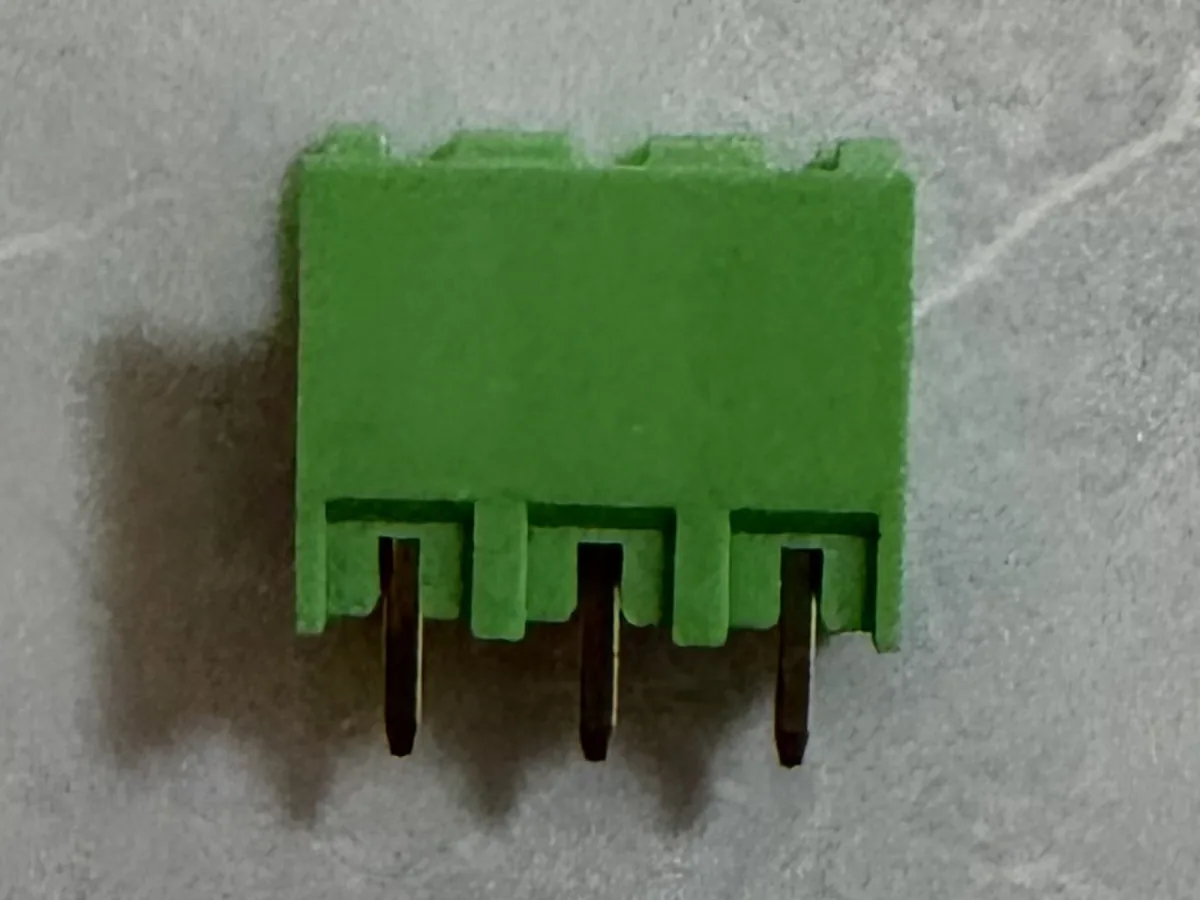
KF2EDG-5.08
5.08mm pluggable terminal block
- Pitch
- 5.08mm
- Mounting
- Vertical PCB mount
- Rated current
- 15A (UL) / 20A (IEC)
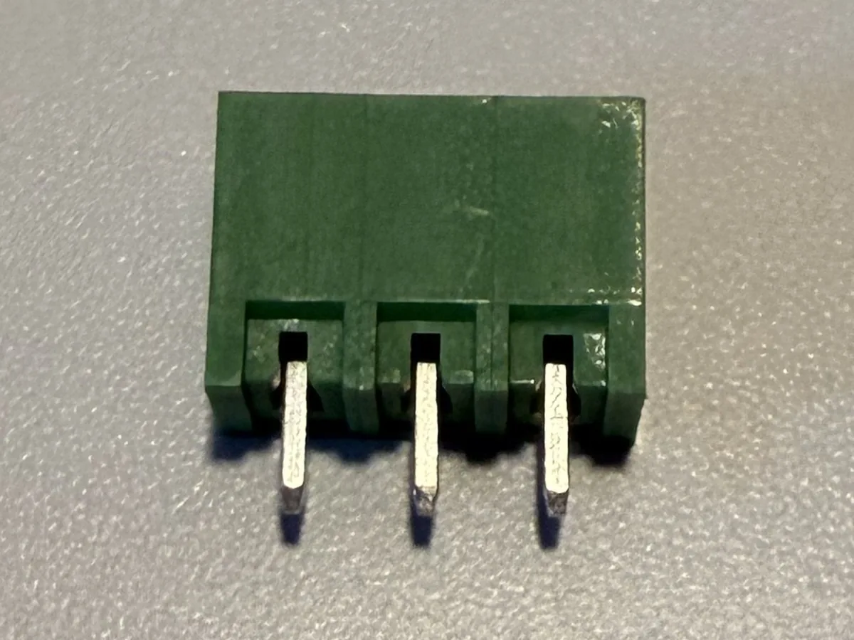
KF2EDG-5.08 Pin Header
Male pin header
- Pitch
- 5.08mm
- Mounting
- Vertical PCB mount
- Rated current
- 15A (UL) / 20A (IEC)
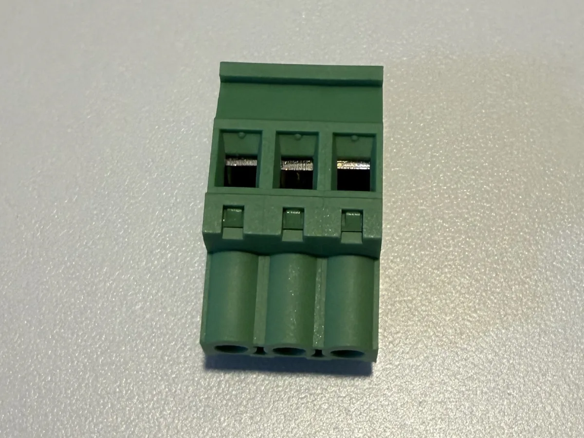
KF2EDGKA(B)-5.08
A/B latch options for multiple locking configurations
- Pitch
- 5.08mm
- Mounting
- Vertical PCB mount
- Rated current
- 15A (UL) / 20A (IEC)
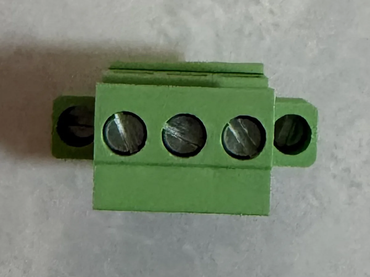
KF2EDGKA(B)M-5.08
A/B latch options with mounting flange
- Pitch
- 5.08mm
- Mounting
- Vertical PCB mount
- Rated current
- 15A (UL) / 20A (IEC)
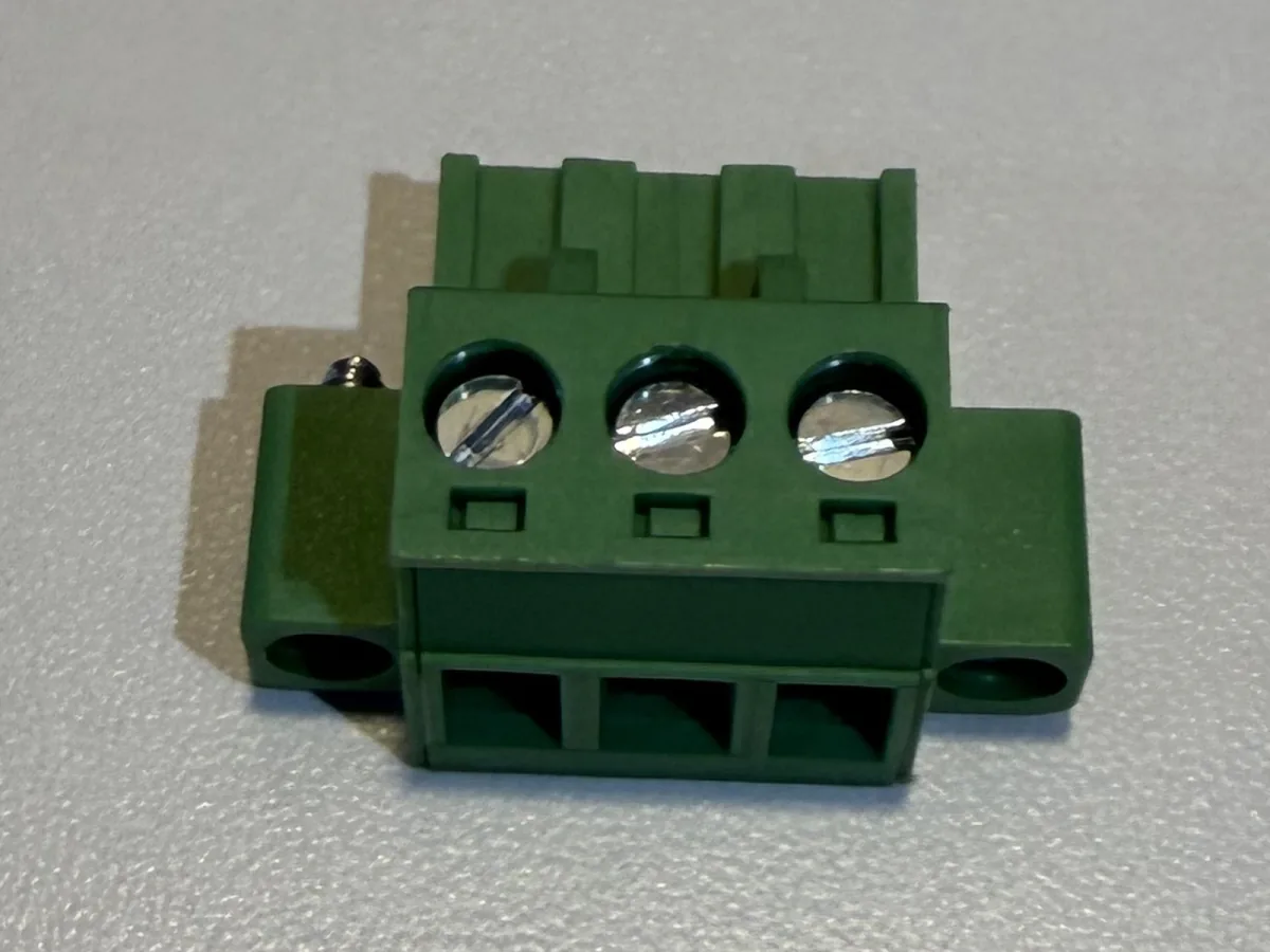
KF2EDGKM-5.08
Locking latch with mounting flange
- Pitch
- 5.08mm
- Mounting
- Vertical PCB mount
- Rated current
- 15A (UL) / 20A (IEC)
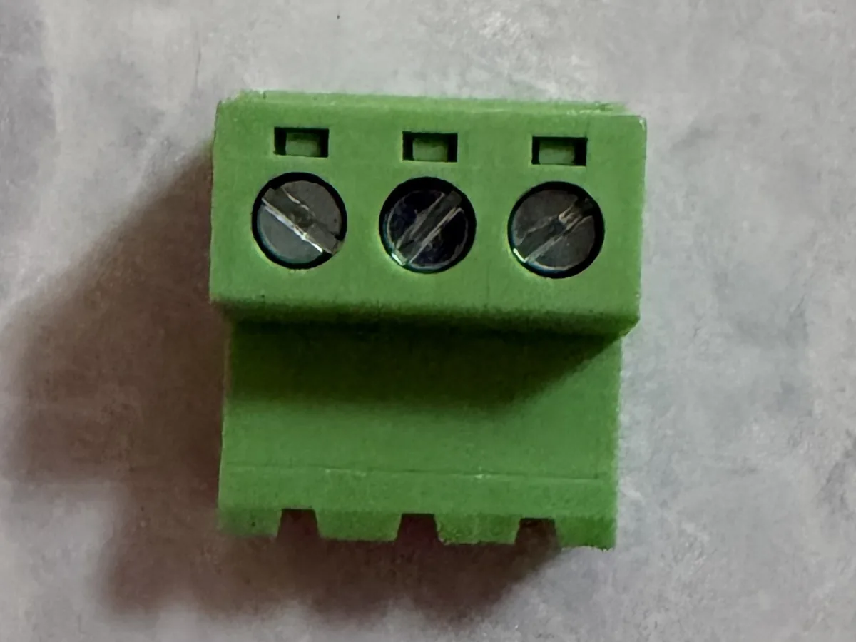
KF2EDGRK-5.08
Right-angle pins with locking latch
- Pitch
- 5.08mm
- Mounting
- Right-angle PCB mount
- Rated current
- 15A (UL) / 20A (IEC)
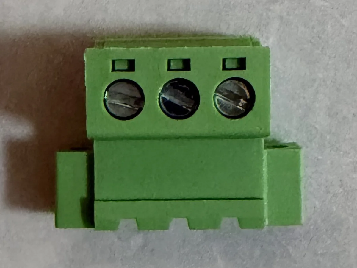
KF2EDGRKP-5.08
Right-angle pins, locking latch and mounting flange
- Pitch
- 5.08mm
- Mounting
- Right-angle PCB mount
- Rated current
- 15A (UL) / 20A (IEC)
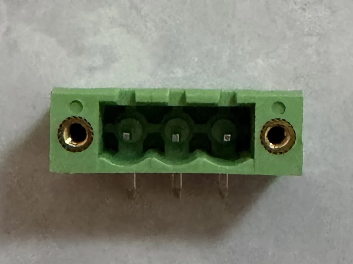
KF2EDGRP-5.08 Pin Header
Right-angle male pin header with mounting flange
- Pitch
- 5.08mm
- Mounting
- Right-angle PCB mount
- Rated current
- 15A (UL) / 20A (IEC)
PCB Screw Terminal Blocks
2 current 5.08 mm references
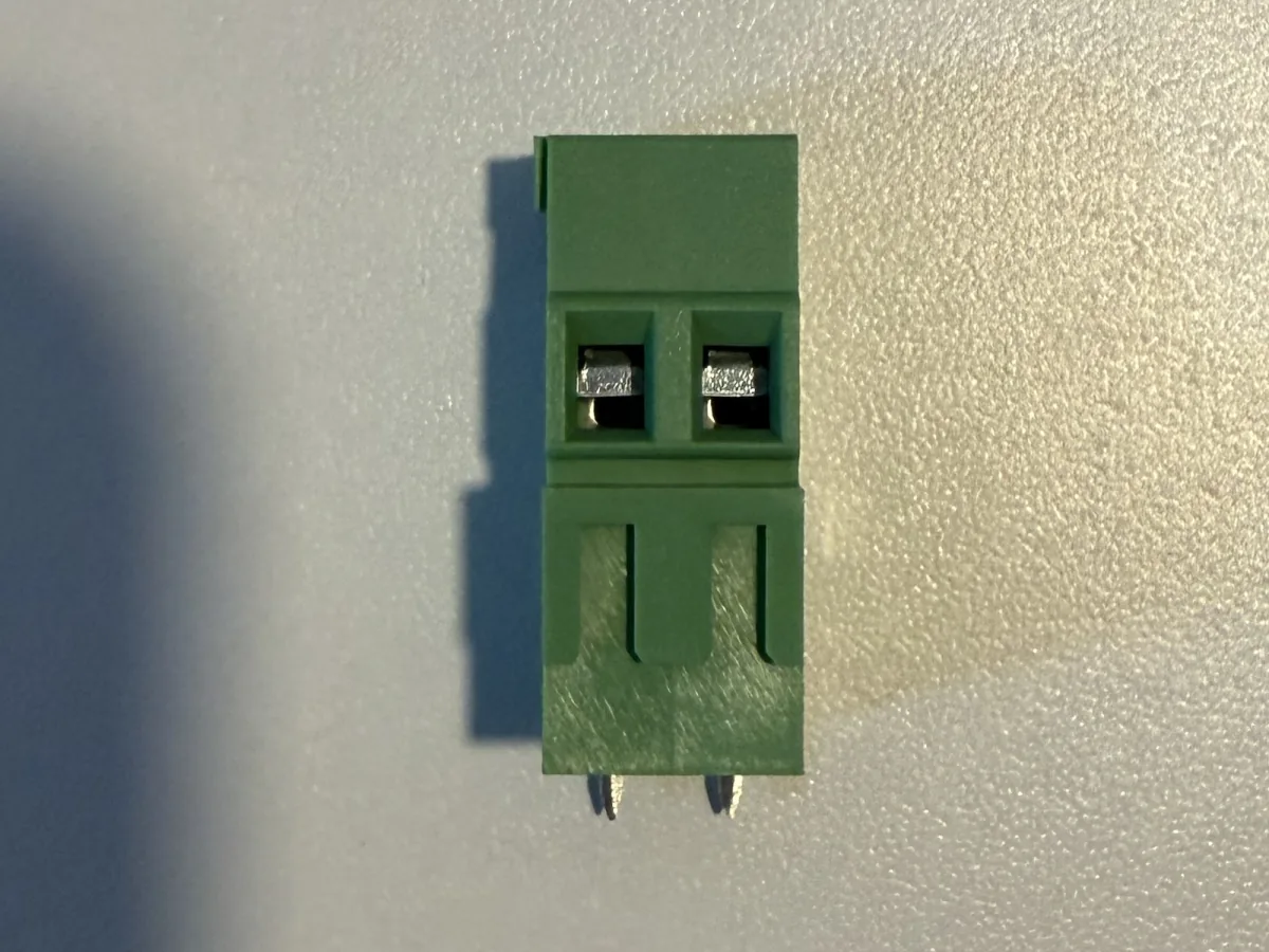
KF128H-5.08
Raised housing designed for increased creepage distance
- Pitch
- 5.08mm
- Mounting
- Vertical PCB mount
- Rated current
- 15A
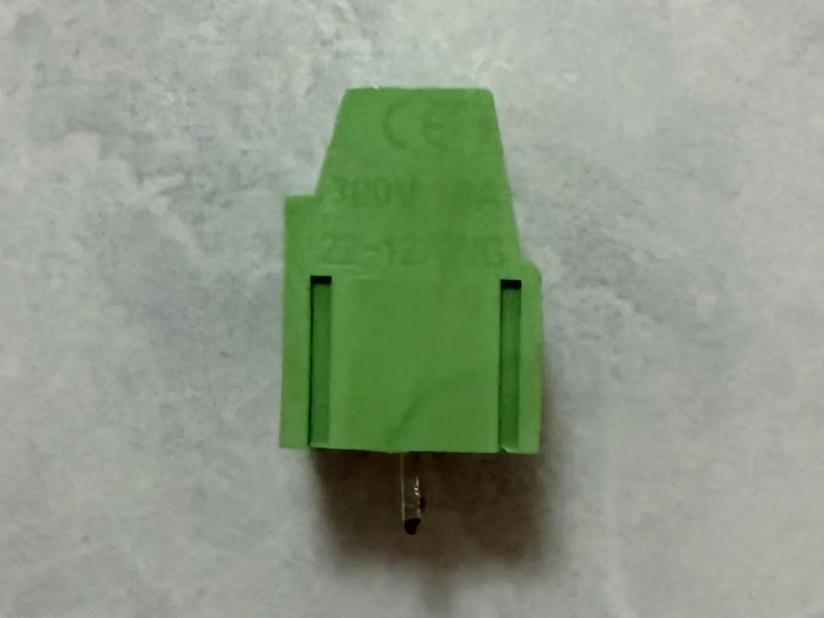
KF128L-5.08
Low-profile design for space-constrained layouts
- Pitch
- 5.08mm
- Mounting
- Vertical PCB mount
- Rated current
- 15A
Spring Terminal Blocks
4 current 5.08 mm references
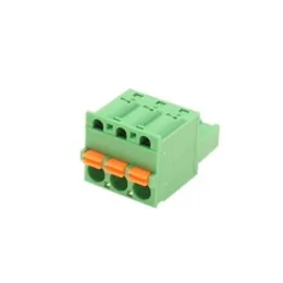
KF2EDGKD-5.08
Spring-clamp connection; technical data pending supplier confirmation.
- Pitch reference
- 5.08 mm
- Data status
- Technical data pending
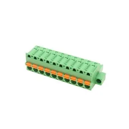
KF2EDGKDM-5.08
Spring-clamp connection; technical data pending supplier confirmation.
- Pitch reference
- 5.08 mm
- Data status
- Technical data pending
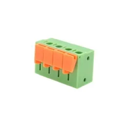
KF142R-5.08
Spring-clamp connection; technical data pending supplier confirmation.
- Pitch reference
- 5.08 mm
- Data status
- Technical data pending
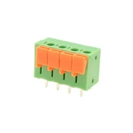
KF142V-5.08
Spring-clamp connection; technical data pending supplier confirmation.
- Pitch reference
- 5.08 mm
- Data status
- Technical data pending
5.08 MM BUYER FAQ
Use exact pitch as one filter—not the final approval.
How many current YIHENTRA models are listed at 5.08 mm pitch?
The current catalog contains 14 references whose supplied pitch field explicitly includes 5.08 mm: 10 with documented model data and 4 Spring references with technical fields still pending confirmation.
Is a 5.08 mm terminal block interchangeable with any other 5.08 mm model?
No. Matching pitch does not prove the same positions, PCB footprint, pin layout, mounting, wire entry, mating role, keying, retention, conductor acceptance, ratings or approvals.
Is 5.08 mm the same as 5.0 mm pitch?
No. They are different nominal center spacings. The 0.08 mm difference accumulates across multiple intervals, and the full housing, pins and mating geometry must also be checked.
Why are some 5.08 mm Spring model ratings not shown?
The supplied Spring source set identifies the model and pitch but does not provide enough confirmed model-level electrical, conductor and mounting data. Those fields remain pending rather than being inferred.
What should I send for a 5.08 mm terminal block quotation?
Send the application, exact model or existing part, positions and rows, mounting and mating role, PCB drawing, conductor conditions, current and voltage basis, sample and production quantity, target market and required documents.