
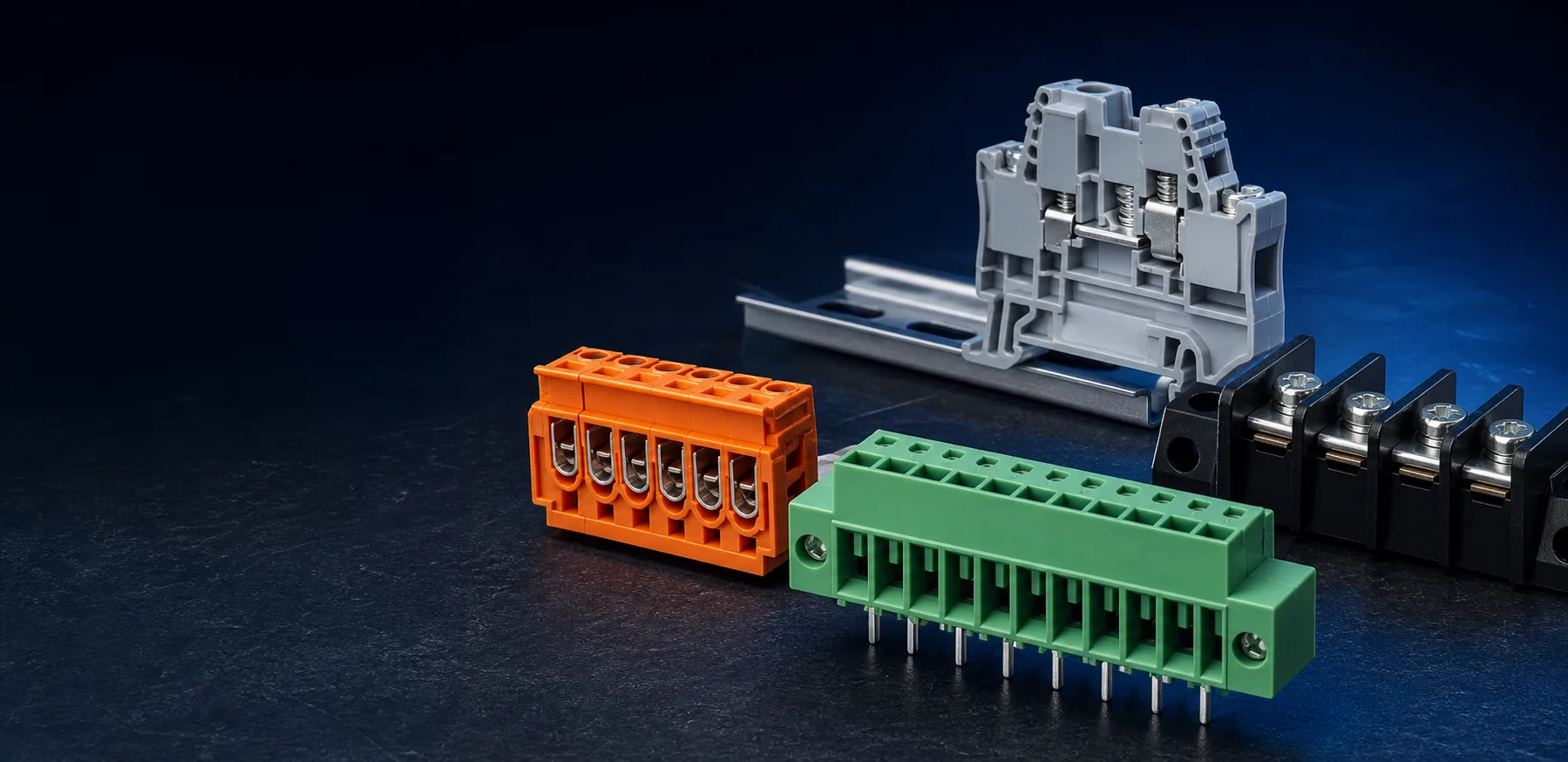
A terminal block can look correct and still fail the design review because the pitch, footprint, wire entry, conductor range, rating or mating geometry is wrong. The safest workflow is to select from verified requirements rather than appearance.
01 / CONNECTION ARCHITECTURE
Choose how the conductor should meet the PCB or equipment.
Start with the assembly and service requirement. A direct PCB screw terminal, a pluggable pair, a barrier form and a spring-clamp connection solve different wiring problems even when their pitch or current range overlaps.
Pluggable Terminal Blocks
Serviceable wire-to-board connections where the wiring harness may need to disconnect from the PCB.
Explore 23 models →02PCB Screw Terminal Blocks
Direct screw-clamp wire-to-board connections with no separate mating plug.
Explore 14 models →03Barrier Terminal Blocks
Partitioned screw positions used in equipment and power-wiring layouts.
Explore 5 models →04Spring Terminal Blocks
Spring-clamp or push-button connection requirements where the exact actuation form matters.
Explore 11 models →02 / EIGHT SELECTION CHECKS
Turn the application into eight verifiable inputs.
- 01
Connection architecture
Decide whether the wiring should connect directly to the PCB, disconnect through a plug and header, use a partitioned barrier form, or use a spring-clamp mechanism.
- 02
Pitch
Measure the center-to-center spacing of adjacent contacts. Check the complete PCB footprint; a small pitch difference accumulates over multiple positions.
- 03
Positions
Specify the required pole count and whether the housing is fixed, interlocking or part of a mating plug-and-header system.
- 04
Mounting & wire entry
Confirm vertical or right-angle PCB mounting, conductor entry direction, enclosure clearance and access for assembly or service.
- 05
Conductor range
State conductor type and cross-section or AWG range. Strip length, ferrule use and termination instructions must follow the exact product data.
- 06
Current & voltage
Use the rating for the exact model, applicable standard and operating condition. Do not transfer a family-level or similar-product value to another part.
- 07
Mechanical details
Check housing dimensions, pin layout, screw or actuation access, latch, flange, cover, keying and any required tightening information.
- 08
Documents & sample
Define the target market and required drawings, material information and compliance documents, then verify PCB fit and mating with a sample before approval.
03 / PITCH & MATING
A near match is not a confirmed match.
Pitch is measured from the center of one position to the center of the next. A small difference between two nominal pitches grows across a multi-position connector, so the complete footprint must be checked instead of one gap.
Do not treat them as automatically interchangeable. Confirm the drawing, total span, solder-pin layout, housing geometry and — for pluggable parts — the matching plug or header.
Compare center spans with the 5.0 vs 5.08 mm pitch calculator →Mating compatibility also depends on contact geometry, orientation, keying, latch and housing tolerances. A reference model or clear photos help narrow the search, but physical sampling remains the final practical check.
04 / FAMILY COMPARISON
Compare the useful distinction, then verify the exact part.
Serviceable wire-to-board connections where the wiring harness may need to disconnect from the PCB.
Plug/header mating pair, pitch, orientation, keying, latch, flange and PCB footprint.
Direct screw-clamp wire-to-board connections with no separate mating plug.
Pitch, wire entry, positions, conductor range, tightening information and board clearance.
Partitioned screw positions used in equipment and power-wiring layouts.
Terminal spacing, cover requirement, mounting direction, conductor range and installation access.
Spring-clamp or push-button connection requirements where the exact actuation form matters.
Conductor type, actuation method, pitch, positions, footprint and confirmed model-level ratings.
05 / RFQ CHECKLIST
Send enough detail to receive a useful shortlist.
Equipment type, PCB use and operating context
Existing model, drawing or clear product photos
Connection family, pitch, positions and mounting direction
Wire range, current, voltage and target market
Sample quantity, estimated volume and required timing
Drawing, material data and requested compliance files
06 / COMMON MISTAKES
Six shortcuts that create avoidable rework.
- 01
Matching only by color or housing appearance.
- 02
Treating 5.0 mm and 5.08 mm pitch as automatically interchangeable.
- 03
Selecting a pluggable part without confirming its mating header or plug.
- 04
Using a current or voltage value copied from a related model.
- 05
Ignoring wire-entry direction, enclosure clearance or tool access.
- 06
Approving production before checking the drawing, PCB footprint and sample.
07 / BUYER FAQ
PCB terminal block selection questions.
What is terminal block pitch?
Pitch is the center-to-center distance between adjacent electrical positions. It must match the PCB footprint and, for pluggable systems, the mating component.
Are 5.0 mm and 5.08 mm terminal blocks interchangeable?
Do not assume so. The spacing difference accumulates across positions, and pin, housing, keying and mating geometry may also differ. Check the exact drawing and sample.
Which rating should be used when several values are listed?
Use the rating that applies to the exact model, conductor, target market, standard and operating condition. Confirm the final data and required documents before approval.
When is a pluggable terminal block preferable?
It is useful when the field wiring should disconnect from the PCB for assembly or service. The plug and header must still be selected and sampled as a mating pair.
What should be included in a terminal block RFQ?
Include the application, reference model, connection type, pitch, positions, mounting direction, conductor range, current, voltage, quantity, target market and requested documents.